2-Wire vs 3-Wire vs 4-Wire RTD: Understanding PT100 & PT1000 Sensor Accuracy
Nov 25, 2025Updated October 1, 2026. Reviewed by the Focusens Engineering Team.
| Configuration | Leads | How it connects | What it does about lead resistance |
|---|---|---|---|
| 2-wire | One lead at each end of the element | Both leads carry the excitation current and are also the measurement leads | Nothing; both leads add to the reading |
| 3-wire | Two leads at one end, one at the other | The extra lead lets the instrument measure one lead and subtract it | Cancels the lead resistance as long as the leads match |
| 4-wire | Two leads at each end | One pair carries the current, the other pair measures the voltage across the element | Removes lead resistance from the measurement |
IEC 60751:2022, the international standard for industrial platinum RTDs, ties accuracy to the wiring. Clause 5.5 states that thermometers of a tolerance class "better than class B shall have 3-wire or 4-wire configuration", with the "4-wire configuration being recommended" (IEC 60751:2022 preview, IEC webstore). Under IEC 60751:2022, a 2-wire probe therefore cannot be declared better than Class B, even if the element inside it is Class A or AA.
3-wire is the industrial default because it removes most of the lead error with one extra conductor. Its limit is that it assumes the leads are identical; Emerson's Rosemount 248 manual notes that a 3-wire connection "cannot compensate for imbalances". How large that imbalance error gets, and how much 2-wire cable adds, is worked through in our page on RTD lead resistance error.
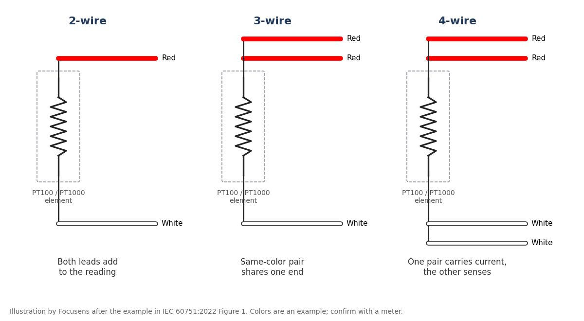
In the IEC 60751:2022 example, leads at the same end of the element share a color.
| Configuration | IEC 60751:2022 Figure 1 (also Emerson 214C, JIS C 1604) | Second element in a duplex probe |
|---|---|---|
| 2-wire | Red, white | Black, yellow |
| 3-wire | Red, red, white | Black, black, yellow |
| 4-wire | Red, red, white, white | Black, black, yellow, yellow |
Figure 1 of the standard covers one and two elements, with "Black (Grey)" for the second element. Emerson's Rosemount 214C quick start guide shows the same scheme as "RTD Lead Wire Configuration per IEC 60751", and pt100.de describes the same DIN EN 60751 coding, with "yellow and black or grey" for the second sensor. Japan's JIS C 1604, which follows IEC 60751, moved to the same scheme in its 2013 revision; the Japanese RTD maker Okazaki notes the change from the older red-white-white.
The standard presents this identification only as "a typical example" (clause 5.5), so the colors are an example, not a requirement. Some online answers say IEC 60751 uses two white leads and one red; IEC 60751:2022 Figure 1 shows the reverse: two red and one white.
US practice is not uniform either. National Instruments' knowledge base says RTDs "typically come in red/black or red/white color combinations", with red as excitation, and its 3-wire instructions use one red lead and two black or white leads (NI knowledge base). Thermometrics describes "two white wires and one red wire". On a 2010 Mike Holt forum thread asking "Are there color code standards for RTD's?", one forum member replied "There is no standard that I know of", listing 3-wire probes received as white/red/red, yellow/red/red and white/white/red. Two probes in the same panel can therefore use opposite colors for the same function. His fix was to put "functional names on the Terminal Block so they get wired correctly, like T+, T-, T-."
In most schemes, leads that share a color share an end, but not all: Anderson's sealed-cable probes use red and white as the two common leads and green as the single signal lead (Anderson manual). Treat color as a hint and the meter as proof.
| Element temperature | PT100 | PT1000 |
|---|---|---|
| 0 °C | 100.00 Ω | 1000.0 Ω |
| 20 °C | 107.79 Ω | 1077.9 Ω |
| 25 °C | 109.73 Ω | 1097.3 Ω |
| 30 °C | 111.67 Ω | 1116.7 Ω |
PT100 values are from the IEC 60751 numerical table (Table 1 in the 2008 edition, Annex A in 2022), which lists every degree; PT1000 values are ten times the PT100 values for IEC 60751 elements (α = 0.00385). Full tables are in our PT100 resistance table and PT1000 resistance table.
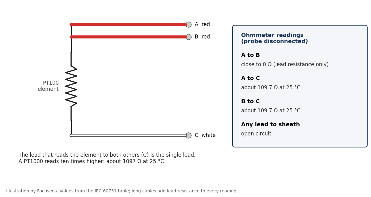
A reading of about 110 Ω on a probe at room temperature means a PT100, and about 1100 Ω means a PT1000. An open circuit between any pair means a broken lead or element; a reading well below the table value between opposite-end leads can mean moisture in the probe or a short between conductors.
Terminal names differ by maker, and so does which side takes the same-end pair. These are three examples from manufacturer documentation.
| Input | Terminal names | 3-wire connection | 2-wire connection |
|---|---|---|---|
| Rockwell 1769-IR6 | EXC, SENSE, RTN per channel | Same-end pair to EXC and SENSE, single lead to RTN (3-wire figure, p. 41) | Add the jumper shown in the manual's 2-wire figure (p. 41) |
| Siemens S7-1500 AI 8xU/I/RTD/TC ST | Mn+ / Mn− measuring input, Ic n+ / Ic n− current output | Same-end pair to Mn− and Ic n−; single lead to Ic n+, jumpered to Mn+ (Figure 3-5, p. 18); the following odd channel must be deactivated | Not available for RTD; 2-wire is listed only for the resistance (PTC) type (section 4.1) |
| Beckhoff EL3202 | +R1, +RL1, −R1 | Uses all three terminals; change the connection setting from its 2-wire default | External bridge required ("for the 2-wire connection an external bridge is necessary") |
The Rockwell manual sets two limits on p. 37: keep lead resistance "less than 25 Ω", and "the resistance difference of the cable lead wires must be equal to or less than 0.01 Ω". The second is the tighter one, and it is about matched conductors.
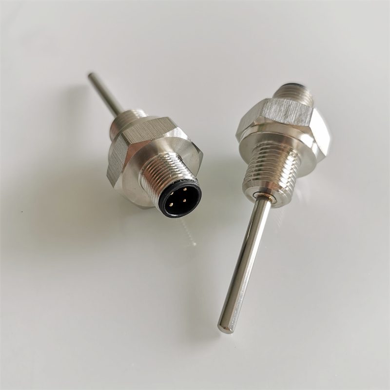
In a duplex probe, each element is wired as its own RTD to a separate input, using its own color set (Emerson 214C, Figure 2-2). Connector pinouts are set by the probe maker, so ask for the connector drawing.
A 4-wire sensor on a 3-wire input. Use three of the four leads and leave the fourth unconnected and insulated. Emerson's Rosemount 644 quick start guide says to use its 4-wire sensors "in three-wire configurations by leaving the unneeded leads disconnected and insulated with electrical tape", and its 214C guide says to "connect only one white lead". Rockwell's 1769-IR6 manual gives the same instruction: "Leave one sensor wire open" (pp. 41 and 42). Schneider Electric's building-automation support adds that the fourth wire "should NOT be connected in parallel" with its partner (Schneider knowledge base).
A 3-wire sensor on a 4-wire input. National Instruments connects the red lead to excitation positive, jumpers excitation positive to channel positive on the DAQ device, and connects one black (or white) lead to excitation negative and the other to channel negative (NI knowledge base). The reading then includes the resistance of the red lead, half the error of a 2-wire connection, unless the input compensates internally; NI notes the NI 9217 does and needs no jumper.
A 2-wire sensor on a 3-wire input. Jumper the input at its terminals, as Rockwell's 2-wire figure shows and Beckhoff describes as an "external bridge". The reading includes both leads. Not every input allows it: the Siemens module above has no 2-wire RTD mode.
Use 2-wire only on short cable where the added error is acceptable; our lead resistance page works out how much by cable length and gauge. Use 3-wire for most industrial and building-services work, with one homogeneous cable so the leads stay matched. Use 4-wire for probes declared Class A or better, for calibration work, and wherever joints or terminals in the run could unbalance a 3-wire connection. A PT1000 cuts every lead-related error to a tenth of a PT100's; our PT100 vs PT1000 comparison covers when that matters, and our page on what a drive reads when the sensor type is wrong covers PT1000 inputs on motor drives.
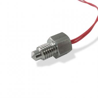
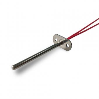
Our RTD probes are built with PT100, PT500 or PT1000 elements in IEC 60751 Class A or B, with PVC, PTFE, silicone or fiberglass cable. Our product pages do not specify lead colors, and they list 2-wire, 3-wire and 4-wire versions. Put the configuration and color scheme your panel uses on the inquiry, and check both on the approval drawing; a Class A probe should be ordered as 3-wire or 4-wire. See the RTD sensor range, including the Class A PT1000 3-wire probe, the PT100/PT1000 3-wire or 4-wire probe, the PT100 2-wire or 3-wire probe, thread-mount PT100 and PT1000 probes and the crimped metal-housing PT sensor. For the element itself, see what an RTD is and what its tolerance classes promise.
On most 3-wire RTDs the two leads of the same color are joined to the same end of the element; together they form the common or compensating pair. The single lead of the other color connects to the other end. Some makers differ (Anderson pairs red with white). Confirm with a meter: the common pair reads close to 0 Ω.
In the example in IEC 60751:2022 Figure 1, a 3-wire RTD has two red leads and one white lead. Some US manufacturers use one red and two white, so check the probe's data sheet or measure it.
Yes. Colors, terminals and meter checks are the same; readings are ten times higher, about 1097 Ω at 25 °C, and the input must be set to PT1000. The same lead resistance causes one tenth of the error.
An RTD has 3 wires so the instrument can measure the resistance of one lead and subtract the lead resistance from the reading. This cancels most of the cable error with one extra conductor, provided the leads are matched.
A 3-wire RTD can be used on a 2-wire input by connecting one of the same-end pair and the single lead and leaving the third lead insulated. Emerson's 214C guide says to "connect matching colored wires first and then connect the paired wires to the terminal", which halves the resistance of that leg. The reading still includes lead resistance, as any 2-wire connection does.
On a 4-wire RTD, one lead at each end of the element carries the excitation current and the other lead at each end measures the voltage across the element. Because almost no current flows in the sense leads, their resistance does not enter the reading. In the IEC 60751:2022 Figure 1 example the leads are red, red at one end and white, white at the other.
To check a 3-wire RTD, measure all three pairs of leads. Two pairs should read the element, about 109.7 Ω for a PT100 at 25 °C, and the same-end pair should read close to 0 Ω.
Reviewed by the Focusens Engineering Team on October 1, 2026. Wiring rules and terminal names come from IEC 60751, JIS C 1604 and the Emerson, Rockwell, Siemens, Beckhoff, National Instruments, Schneider Electric and Anderson documents linked beside each point. The wiring diagrams are illustrations, and the control-cabinet scene is AI-generated. No reading on this page is a measurement taken on a Focusens part.
No.1 XiSan Road, Electromechanical Industry Park , High&New Tech.Zone. Hefei,Anhui,China
teléfono : +86-551-69109668
Whatsapp : +86-13339100504
Email : info@focusens.com
Skype : melodyliu520






 +86-551-69109668